Previously, we have provided a tutorial on molecular dynamics (MD) simulation of a protein using GROMACS [1] and its result analysis [2]. In this article, we will perform MD simulation for a protein-ligand complex using GROMACS [3, 4].
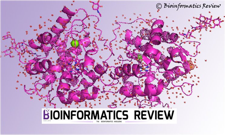
In this tutorial, we are going to simulate chain A of Human Serum Albumin (HSA) complexed with CMPF (PDB ID: 2BXA). At first, we will extract ligand coordinates from the complex then prepare the protein and ligand topology separately, and later the complex will be simulated using the CHARMM36 force field. The protein-ligand complex simulation is explained in the following steps.
1. Preparing input file
Open the downloaded complex PDB file in an editor and remove chains except for Chain A and save the file. Do not remove HETATOMS. Note down the residue name of the ligand present in the fourth column of the HETATOM section. In this case, it is C1F.
2. Extracting ligand coordinates
Open a terminal (Ctrl+Alt+T) and type the following command:
$ grep C1F 2bxa.pdb > c1f.pdb
Now, remove all C1F lines from the 2bxa.pdb file.
3. Preparing Force Field
As mentioned above, we will simulate the complex under the CHARMM36 force field. Download and untar the file as shown below:
$ wget http://mackerell.umaryland.edu/download.php?filename=CHARMM_ff_params_files/charmm36-mar2019.ff.tgz
$ tar xvzf charmm36-mar2019.ff.tgz
You will see a subdirectory “charmm36-mar2019.ff” created in your working directory.
4. Generating topology of the protein (HSA)
For this, the pdb2gmx module will be used.
$ gmx pdb2gmx -f 2bxa.pdb -o 2bxa_processed.gro -missing
You will be prompted to select the force field. Select option 1, listed under ‘From current directory’. Later, it will prompt you to choose a water model, you can select the default model (TIP3P).
If you get any error during this step, then open SwissPDB Viewer, open this pdb file, and save it in .pdb format.
5. Preparing the ligand (C1F) file
We will convert the ligand file into .mol2 format (explained in the next step).
The ligand file, c1f.pdb will be processed using the Avogadro program [5, 6] and then converted to .mol2 format as shown below:
- Open Avogadro
Open --> c1f.pdb- Go to
Build --> Add Hydrogens - Go to
File --> Save as --> SYBYL mol2 - Save it as c1f.mol2.
The c1f.mol2 file needs to be corrected before subjecting to topology generation.
Open the c1f.mol2 file in an editor and do the following:
- Replace “*****” with C1F as shown below (after step-4).
- Make sure the residue name and numbers are the same.
- Look into the @<TRIPOS>BOND section. We need to correct the bond order using a Perl script available here.
- Run the Perl script as
$ perl sort_mol2_bonds.pl c1f.mol2 c1f_clean.mol2
@<TRIPOS>MOLECULE
JZ4
Now, we will use c1f_clean.mol2 file to generate the topology.
6. Generating ligand topology
This is one of the important steps in the MD simulation of a complex. It is also difficult to deal with bound ligands in MD simulation. Therefore, automated programs will be used in creating a topology of the ligand. There are different software available for different types of force fields as shown below:
AMBER – Antechamber & acpype
CHARMM – CGenFF
OPLS-AA – TopolBuild & LigParGen
GROMOS87/GROMOS96 – PRODRG 2.5 & ADG
We will use the CGenFF server [7] in this tutorial. Register and create a free account on this server. After uploading and submitting the c1f_clean.mol2 file, it will give c1f_clean.str file as output. Download the file.
Now, since the C1F topology is in CHARMM format, we need to convert to gmx to use in GROMACS for simulation. For that, download the “cgenff_charmm2gmx.py” script from here and run it as shown below:
$ python cgenff_charmm2gmx.py C1F c1f_clean.mol2 c1f_clean.str charmm36-mar2019.ff
If there is no error, it will display:
============ DONE ============
Conversion complete.
The molecule topology has been written to c1f.itp
Additional parameters needed by the molecule are written to c1f.prm, which needs to be included in the system .top
============ DONE ============
The ligand topology is now written to ‘c1f.itp’.
7. Building the protein-ligand complex
For that, we will use 2bxa_processed.gro and c1f_ini.pdb files.
$ gmx editconf -f c1f_ini.pdb -o c1f.gro
Now, copy 2bxa_processed.gro file to a new file and save it as complex.gro. Open complex.gro in an editor and edit as shown below:
- Copy coordinates section of c1f.gro.
- Paste it into the complex.gro file below the last line of protein atoms and before box vectors as shown below:
582ALA OT1 8974 0.255 2.404 -3.026
582ALA OT2 8975 0.273 2.370 -2.964
1C1F C1 1 0.472 -1.164 0.905
1C1F C2 2 0.404 -1.080 0.817
1C1F C3 3 0.474 -1.098 0.696
1C1F C4 4 0.450 -1.035 0.559
1C1F C6 5 0.444 -1.191 1.055
1C1F O 6 0.566 -1.178 0.713
1C1F C7 7 0.526 -1.527 0.872
1C1F C9 8 0.558 -0.933 0.524
1C1F C11 9 0.679 -1.324 0.872
1C1F C40 10 0.572 -1.222 0.829
1C1F C12 11 0.652 -1.463 0.812
1C1F C70 12 0.559 -0.905 0.373
1C1F O1 13 0.214 -0.945 0.750
1C1F C13 14 0.281 -0.988 0.843
1C1F O2 15 0.247 -0.957 0.957
1C1F O3 16 0.662 -0.914 0.308
1C1F O4 17 0.455 -0.872 0.316
1C1F H1 18 0.450 -1.112 0.485
1C1F H2 19 0.356 -0.983 0.562
1C1F H3 20 0.360 -1.132 1.086
1C1F H4 21 0.530 -1.164 1.112
1C1F H5 22 0.423 -1.295 1.069
1C1F H6 23 0.511 -1.623 0.827
1C1F H7 24 0.441 -1.464 0.852
1C1F H8 25 0.538 -1.538 0.978
1C1F H9 26 0.539 -0.841 0.576
1C1F H10 27 0.654 -0.972 0.552
1C1F H11 28 0.775 -1.291 0.839
1C1F H12 29 0.676 -1.333 0.979
1C1F H13 30 0.639 -1.453 0.707
1C1F H14 31 0.735 -1.526 0.836
1C1F H15 32 0.295 -0.988 1.031
1C1F H16 33 0.375 -0.864 0.364
5.94821 9.25525 7.10469
Since we have added ligand atoms in the complex.gro file, therefore, we will increase the number of atoms in the second line of the complex.gro file. As you can see, there are 8975 atoms before addition. Now, edit this and write 9008 (8975+33).
8. Building the topology of complex
Now, we will introduce the ligand in the system topology by inserting a line as shown below:
- Open topol.top.
- After the position restrain file is included, add
#include "c1f.itp"as shown below:
; Include Position restraint file
#ifdef POSRES
#include "posre.itp"
#endif

; Include ligand topology
#include "c1f.itp"

; Include water topology
#include "./charmm36-mar2019.ff/tip3p.itp"
3. At the top of topol.top, add the parameters previously written to the c1f.prm file. After force field parameters, insert #include "c1f.prm"as shown below:
; Include forcefield parameters
#include "./charmm36-mar2019.ff/forcefield.itp"

; Include ligand parameters
#include "c1f.prm"

[ moleculetype ]
; Name nrexcl
Protein_chain_A 3
4. Now, go to the [molecules]directive and add C1F as shown below:
[ molecules ]
; Compound #mols
Protein_chain_A      1
C1F                  1
Now, we have prepared the topology of the complex completely. We can move to the next step.
9. Defining box
From this point forward, the simulation of the protein-ligand complex is similar to any other MD simulation. Now, we will define a unit cell.
$ gmx editconf -f complex.gro -o box.gro -c -d 2.0 -bt dodecahedron
here, -f defines the input filename, -o is the output file, -c is used to keep the protein in the center inside the box, -d defines the distance of the protein from the box edges (which should be at least 1.0 nm to avoid the periodic images of protein otherwise, the forces could be miscalculated), and -bt is the type of box.
10. Solvating the complex
Now, we will fill the box with water using the solvate module which keeps track of the newly added water molecules and writes to the topology file.
$ gmx solvate -cp box.gro -cs spc216.gro -o complex_solvate.gro -p topol.top
here, -cp defines the protein configuration obtained in the last step, -cs is the solvent configuration which is a part of GROMACS, -o defines the name of the output file, and -p is the topology file.
Now, if you open the topol.top file, you will find SOL molecules at the end of the file as shown below. The topology file will not be updated in case a non-water solvent is used.
[ molecules ]
; Compound #mols
Protein_chain_A 1
C1F 1
SOL 52450
11. Adding ions
Now, we need to add ions to the charged protein by using the genion module. It requires a grompp module to produce a .tpr file which is used as an input to the genion command. First, we need an MD parameter (.mdp) file which contains all the coordinates and topology information to generate a .tpr file. The ions.mdp file can be downloaded from here. Since we are using the Verlet scheme, therefore, we have to set the nstlist to >=10. Open ions.mdp, change nstlist = 1 to nstlist=10.
As you can see in ions.mdp file, we have defined the periodic boundary conditions (PBC) which are used to minimize edge effects in a finite system, so that there are no boundaries in the system. The artifact caused by the boundaries is now replaced by the PBCs [4]. After that you can see, verlet cut-off scheme has been preferred over the groups of atoms because it offers several advantages such as it works well for the systems where energy conservation is necessary and also works well on CPUs with SSE and AVX.
Let’s generate .tpr file and then add ions.
$ gmx grompp -f ions.mdp -c complex_solvate.gro -p topol.top -o ions.tpr
$ gmx genion -s ions.tpr -o complex_solvate_ions.gro -p topol.top -neutral
It will prompt to select a group of solvent molecules, choose “Group 13- SOL” to embed ions.
In the genion command, -s defines the structure file as input, -o defines the output file, -p is the topology file, and -neutral is defined to add only the necessary ions to neutralize the net charge on the protein. If you look at the terminal, it would be showing you the exact number of ions added whether positive or negative. That’s because if you check the very first topol.top file and look the [atoms] section at the last line, it would be showing the total charge on the protein as “qtot -2”. In this case, it is -2, therefore, it has added 2 NA ions and 0 CL ions to neutralize the protein.
Note: In case, you get the following error, then use “charmm36-july2017.ff“, because this error occurs due to the difference in versions used in defining the force field and CgenFF webserver.
Now, if you look again into the topol.top file under the [molecules] directive, it would show the number of ions added.
12. Energy Minimization
Energy minimization is used to stabilize the structure and ensure it has no steric clashes. For this, another input parameter file is required, that can be downloaded from here. First, using the grompp command, we will generate a binary input file, .tpr which contains simulation, structure, and topology parameters.
$ gmx grompp -f em.mdp -c complex_solvate_ions.gro -p topol.top -o em.tpr
Now, run the energy minimization using mdrun.
$ gmx mdrun -v -deffnm em
It would take a few minutes to finish. In order to know, whether the energy minimization was run successfully, the potential energy must be negative and Fmax must be less than 1000 KJ/mol/nm which was set as the maximum force in em.mdp file. After finishing mdrun, it would look like this:
Steepest Descents converged to Fmax < 1000 in 231 steps
Potential Energy  = -4.9023547e+05
Maximum force     =  8.7591469e+02 on atom 27
Norm of force     =  5.6866214e+01
If the Fmax is greater than that then increase the nsteps for minimization or check the emstep and emtol. Look into the previous tutorial for more components [1].
13. Equilibration
Before running MD, we need to equilibrate the ions and the solvent around the protein and bring the system to a particular temperature at which we want to simulate. After bringing it to a particular temperature, constant pressure is applied to bring it to a proper density. Equilibration is done in two phases: isothermal/isochoric and isobaric.
But before that, we need to restrain the ligand by generating a position restrain topology. For that, create an index group for C1F that contains only its non-hydrogen atoms:
$ gmx make_ndx -f c1f.gro -o index_c1f.ndx

...

> 0 & ! a H*

> q
Now, execute the following command:
$ gmx genstr -f c1f.gro -n index_c1f.ndx -o posre_c1f.itp -fc 1000 1000 1000
Now, we need to add this to the topology. If you simply want to restrain the ligand according to the protein, which means whenever the protein is restrained, then add the following lines to your topology between the ligand topology and water topology. Remember, location matters.
; Include Position restraint file
#ifdef POSRES
#include "posre.itp"
#endif

; Include ligand topology
#include "c1f.itp"

; Ligand position restraints
#ifdef POSRES
#include "posre_c1f.itp"
#endif

; Include water topology
#include "./charmm36-mar2019.ff/tip3p.itp"
If you want to restrain the ligand independently, then define the ligand position restraint file in a different #ifdef block as shown below:
; Include Position restraint file
#ifdef POSRES
#include "posre.itp"
#endif

; Include ligand topology
#include "c1f.itp"

; Ligand position restraints
#ifdef POSRES_LIG
#include "posre_c1f.itp"
#endif

; Include water topology
#include "./charmm36-mar2019.ff/tip3p.itp"
In the second case, do not forget to specify define = -DPOSRES -DPOSRES_LIG in the .mdp file.
After restraining the ligand, we need to merge the ligand and protein. This can be achieved by using the make_ndx module of GROMACS.
$ gmx make_ndx -f em.gro -o index.ndx
On prompt, type 1 & 13 indicating “Protein” & “C1F”.
>1 | 13
>q
Now, we can proceed with equilibration.
i) Phase-I
It is conducted under a constant number of particles, volume, and temperature (NVT ensemble). We will be using another input file, nvt.mdp that can be downloaded from here. The timeframe provided for NVT should bring the temperature of the system to reach a plateau at the desired value. Generally, 100 ps are enough which we will be using here and the temperature will be 300 K. First, we will use grompp command and then mdrun for NVT.
$ gmx grompp -f nvt.mdp -c em.gro -r em.gro -p topol.top -n index.ndx -o nvt.tpr
$ gmx mdrun -v -deffnm nvt
Look into the previous tutorial for more details [1].
ii) Phase-II
After stabilizing the temperature, we should now stabilize the pressure of the system by keeping the number of particles, pressure, and temperature constant (NPT ensemble). We will use a 100 ps timeframe for this phase as well. The npt.mdp file can be downloaded from here. If you look into the npt.mdp file under “Bond parameters”, the “continuation” is set to “yes”, because the simulation is in continuation from Phase-I.
Grompp and mdrun modules will be used in this phase also.
$ gmx grompp -f npt.mdp -c nvt.gro -r nvt.gro -t nvt.cpt -p topol.top -n index.ndx -o npt.tpr
$ gmx mdrun -v -deffnm npt
14. Running MD
We will need an input file md.mdp which can be downloaded from here. We will run a 1 ns MD simulation which is just for the purpose of demonstration otherwise, optimally, 30 ns or 50/60 ns MD simulation is done. 30 ns should be enough but if RMSD is not a straight line then increase the duration of the MD run.
For more details regarding the number of steps, look into the previous tutorial [1].
First, we will generate the .tpr file using grompp and then run production MD.
$ gmx grompp -f md.mdp -c npt.gro -t npt.cpt -p topol.top -n index.ndx -o md_0_1.tpr
$ gmx mdrun -v -deffnm md_0_1
Since MD run takes a long time to finish, therefore, you would like to run for which you can use nohup command as shown below:
$ nohup gmx mdrun -v -deffnm md_0_1
You can check the status by using the command $ jobs or $ top.
If you want to rerun or extend an MD simulation run, then use -cpi and -append options in the mdrun command.
This ends the MD simulation of the protein-ligand complex tutorial. To analyze the MD output, please visit the previously published tutorial [2].
References
- Muniba Faiza (2019). Tutorial: Molecular dynamics (MD) simulation using Gromacs. Bioinformatics Review, 5 (12). (https://bioinformaticsreview.com/20191210/tutorial-molecular-dynamics-md-simulation-using-gromacs/?v=c86ee0d9d7ed)
- Tariq Abdullah (2020). Tutorial: MD simulation output analysis of protein using GROMACS. Bioinformatics Review, 6 (06). (https://bioinformaticsreview.com/20200609/md-simulation-output-analysis-of-protein-using-gromacs/?v=c86ee0d9d7ed)
- Abraham, M. J., Murtola, T., Schulz, R., Páll, S., Smith, J. C., Hess, B., & Lindahl, E. (2015). GROMACS: High performance molecular simulations through multi-level parallelism from laptops to supercomputers. SoftwareX, 1, 19-25.
- Abraham, M. J., Van Der Spoel, D., Lindahl, E., & Hess, B. (2015). the GROMACS Development Team (2014) GROMACS User Manual Version 5.0. 4.
- Avogadro: an open-source molecular builder and visualization tool. Version 1.XX. http://avogadro.cc/
- Marcus D Hanwell, Donald E Curtis, David C Lonie, Tim Vandermeersch, Eva Zurek and Geoffrey R Hutchison; “Avogadro: An advanced semantic chemical editor, visualization, and analysis platform” Journal of Cheminformatics 2012, 4:17.
- Vanommeslaeghe, K., Hatcher, E., Acharya, C., Kundu, S., Zhong, S., Shim, J., … & Mackerell Jr, A. D. (2010). CHARMM general force field: A force field for drug‐like molecules compatible with the CHARMM all‐atom additive biological force fields. Journal of computational chemistry, 31(4), 671-690.


Thanks to your helpful tutorial, I’ve just successfully installed Gromacs on my workstation and then been running MD simulation.
And I would like to share a typo: genstr (x) → genrestr (o)